A HISTORY OF THE MCMATH-PIERCE SOLAR TELESCOPE
CLAUDE PLYMATE
01 June 2001
ABSTRACT
A history of the McMath-Pierce Solar Telescope is presented. The National Science Foundation (NSF) began what would become the Kitt Peak National Observatory in the 1950’s. Dr. Robert R. McMath, a successful businessman turned solar astronomer, chaired an advisory committee to the NSF on the National Observatory. McMath’s interest in solar astronomy was a large factor in the National Observatory including the world’s largest solar telescope among the first telescopes constructed on Kitt Peak. The telescope was named in honor of McMath at its dedication in 1962. It was renamed the McMath-Pierce on the 30th anniversary of the dedication to honor Dr. Keith Pierce, who headed the development of the telescope.
The telescope is of a unique design that is proving valuable even four decades after its construction. It remains the largest aperture solar telescope in existence. The 1.6-meter diameter aperture all-reflecting design of the McMath-Pierce telescope makes it an excellent optical system for the new science of infrared solar astronomy. The McMath-Pierce telescope will likely remain an active research center at the forefront of infrared solar astronomy for many years, until another instrument can surpass its capabilities.
INDEX
1. INTRODUCTION
2. AURA
2.1 Site Selection
3. Dr. ROBERT R. MCMATH
3.1 The McMath-Hulbert Observatory
3.2 R. R. McMath’s Later Years
4. DR. A. KEITH PIERCE
5. OPTICAL CONFIGURATION
5.1 Coude Focus Cassegrain
5.2 Coelostat
5.3 Heliostat
5.4 Unobstructed Optical Design
6. BUILDING DESIGN
6.1 Final Design
6.2 Heliostat Tower
7. TELESCOPE COOLING
7.1 Optical Tunnel Cooling System
7.2 Aboveground Structure Cooling
8. HELIOSTAT WINDSCREEN
9. TELESCOPE OPTICS
9.1 Metal Mirrors
9.2 New Quartz Mirrors
9.3 East And West Auxiliary Heliostats
9.4 The Number 2 Mirror Incident
9.5 Upgrading To Cervit
9.6 Return Of The Quartz Number 2 Mirror
9.7 Integrated Light Feed
10. MIRROR MOUNTS
10.1 Heliostat Mount
10.2 Number 2 Mirror Mount
10.3 Number 3 Mirror Mount
11. COATING LAB
12. INSTRUMENTATION
12.1 Main Spectrograph
12.2 Spectroheliograph
12.3 Solar-Stellar Spectrograph
12.4 Fourier Transform Spectrometer
13. INFRARED CAPABILITY
14. EXAMPLES OF CURRENT PROGRAMS
14.1 Molecular Clouds Over Sunspot Umbrae
14.2 Sodium Emission From Mercury
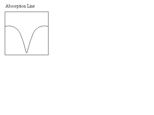
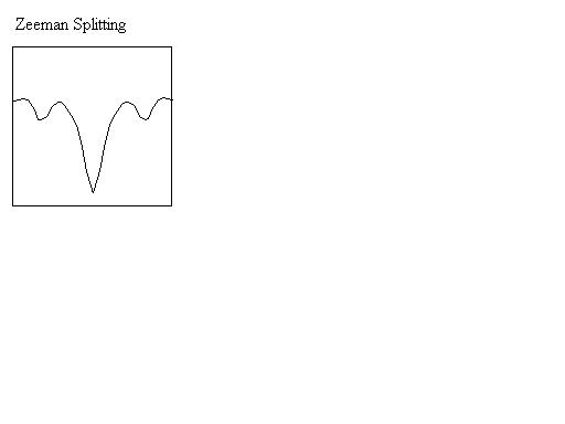
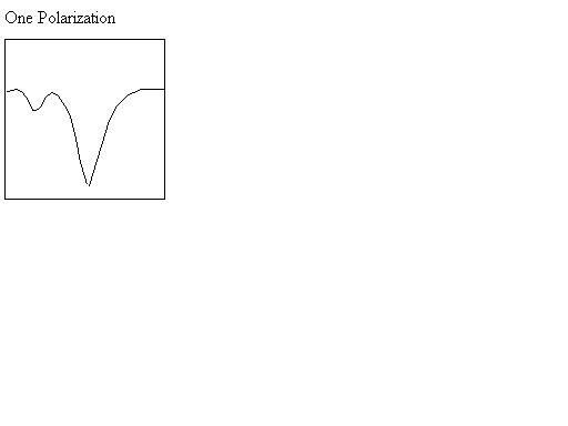
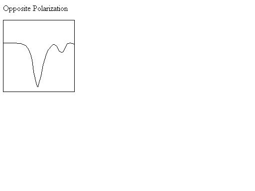
14.3 Zeeman Splitting In OH At 12 Microns
15. THE FUTURE
15.1 A New Infrared Array Detector
15.2 Low Order Adaptive Optics
16. CONCLUSION
REFERENCES
APPENDIX I
APPENDIX II
1. INTRODUCTION
The Sun - nothing can be of a more basic importance. It is the core of our solar system, the life giver. Worshiped as divine throughout history. So basic to our existence that it merits a single-syllable name in many cultures – Ra, Sol, and by us, Sun.
Some may feel that the Sun has lost some of its status in the eyes of modern astronomers. Some talk of it as nothing more than an average star, middle-aged, lost, drifting undistinguished amongst billions of others in our galaxy. They forget how fortunate we truly are to ride round-and-round about such a stable, well-behaved star, that’s nurtured our earth for some 4 ½ billion years, and should continue to watch over us for at least that long again.
 How
does the Sun do this? How can it remain stably bathing the Earth in warmth over
periods measured in billions of years? What can it be like internally where
common descriptive terms and ideas are hopelessly inadequate? These questions
spawned solar astronomy as a branch of astronomy dedicated to the Sun. The
modern era of solar astronomy began around the start of the 20th
century with the construction of the solar telescopes at Mount Wilson. These,
and other solar telescopes that followed, did an admirable job of furthering
our understanding of the inner workings of our star. By mid-century, new
questions had arisen, questions that would require probing deeper with greater
detail. To probe for answers to these questions, an instrument of an entirely
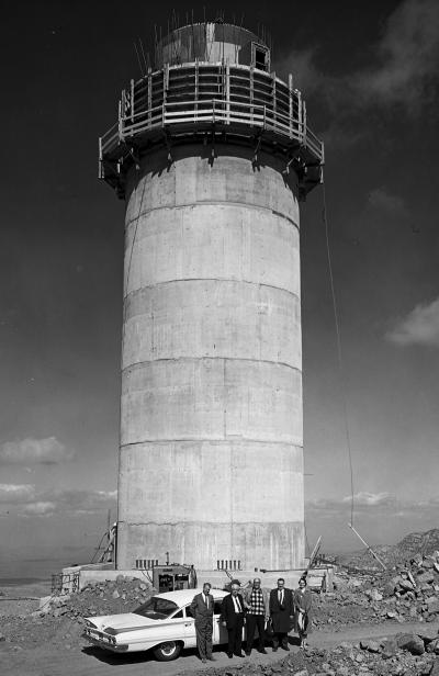
new scale was needed. For this, we built the McMath-Pierce (McMP) Solar
Telescope (Figure 1).
How
does the Sun do this? How can it remain stably bathing the Earth in warmth over
periods measured in billions of years? What can it be like internally where
common descriptive terms and ideas are hopelessly inadequate? These questions
spawned solar astronomy as a branch of astronomy dedicated to the Sun. The
modern era of solar astronomy began around the start of the 20th
century with the construction of the solar telescopes at Mount Wilson. These,
and other solar telescopes that followed, did an admirable job of furthering
our understanding of the inner workings of our star. By mid-century, new
questions had arisen, questions that would require probing deeper with greater
detail. To probe for answers to these questions, an instrument of an entirely
new scale was needed. For this, we built the McMath-Pierce (McMP) Solar
Telescope (Figure 1).
The McMP was dedicated in 1962. It was built as part of the fledgling US National Observatory at Kitt Peak in Arizona. The National Observatory was created with the goal of making world-class astronomical facilities available to the entire astronomical community. The McMP has remained, by far, the largest aperture solar telescope in existence for the past four decades. Only now are plans being formed for a solar telescope to surpass its 1.6-meter aperture.
An unusual all-reflecting optical system was chosen for the McMP. A 2-meter heliostat feeds a beam to an open-air, unobstructed mirror system that produces an image of the Sun that’s roughly 0.8-meters in diameter. This optical design would come to be considered obsolete by many until the 1990’s when infrared array detectors began to become available for astronomical research. The McMP’s all-reflecting optical path became a major asset due to its unique ability to observe the Sun in the infrared. This opened solar physics to the newly available infrared bandpasses. The facility continues to be upgraded with new instrumentation to meet the ever-expanding need of the solar astronomical community. The McMP will remain a vital center for optical and infrared solar astronomy until a new generation solar telescope that can surpass its capabilities replaces it.
Plans are now underway at the National Solar Observatory to develop the Advanced Technology Solar Telescope (ATST). The ATST is to be a 4-meter class, all-reflecting solar telescope that will utilize all of the latest advances in telescope design to achieve the highest possible resolution images of the Sun in both the optical and infrared. Until ATST becomes a reality, the McMP is expected to remain as the premier ground-based facility for infrared solar research and as a primary testbed for ATST technology development.
2. AURA
By the middle of the 20th century, most astronomers began to find themselves in an ever increasingly difficult situation. The world had struggled through two world wars that had created a highly technical society. This new society seemed to have complete faith in the ability of science to solve the world’s problems. Optimism for technology spawned a thriving economy that produced an enormous increase in the numbers of scientists coming out of the universities in all sciences including astronomy.
At the same time, astronomy was becoming truly big science. The size of telescopes had mushroomed through the later 19th and first half of the 20th century. Philanthropists, searching to immortalize themselves, financed ever-larger telescopes to carry their names. This left the handful of largest telescope in the exclusive possession of a few private institutions spread mostly across the US. Yerkes had its 40” refractor, Lick observatory had a 0.9-meter reflector, Mount Wilson housed the 100-inch Hooker telescope and Palomar had the great 5-meter telescope. To compete in cutting-edge science, the astronomer needed access to one of these leading telescopes. If not on the staff of one of the few institutions that had one of the large telescopes of the time, the astronomer would often be without access and at a severe disadvantage.
President Truman signed a bill creating the US National Science Foundation (NSF) on 10 May 1950. The NSF was created to promote basic scientific research in the US. The NSF would act as a conduit for public funding of research grants. In August 1952, the NSF formed what would come to be named the Advisory Panel for Astronomy. The astronomical community was quick to recognize this as a potential source of funding for astronomical research and facilities.
Two conferences on Radio Astronomy were held in Washington, D. C., the first in January 1954 and the second in July of 1956. Out of these conferences grew a proposal to the NSF to fund a National Radio Observatory. The proposal called for universities with an interest in radio astronomy to form a non-profit corporation to construct and manage the facility for the NSF. The proposed name, the Association of Universities for Radio Astronomy (AURA), was changed to the National Radio Observatory and led to the construction of the facility at Green Bank, West Virginia.
Optical astronomers followed a similar path. A proposal was submitted to the NSF to create an astronomical observatory to be operated jointly by the Universities of Arizona, Indiana, and Ohio State. This proposal was submitted on the 15th of May 1952. The proposal was reviewed by the Advisory Panel for Astronomy but formally declined on the 11th of September. The concept of a jointly operated astronomical facility was thought to be a fundamentally good idea. The NSF Advisory Panel for Astronomy responded by establishing an ad hoc Panel on Astronomical Facilities. Dr. Robert R. McMath was selected as chairman of the panel.
The panel arranged for the NSF to sponsor a conference “on photo-electric methods be held to see whether a new facility for such investigations should be established” (Edmondson 1997). The conference was held at Lowell Observatory on the 31 August 1953. All of the larger US observatories as well as observatories of Canada, Australia, and England were represented. McMath’s deteriorating health prevented him from attending, so he asked that Dr. Leo Goldberg be sent in his place to represent the University of Michigan.
Dr. Goldberg believed that the concept of a photoelectric observatory was too limited. At the conference, he made an impassioned plea. “I think what this country needs is a truly National Observatory to which every astronomer with ability and a first class problem can come… I don’t think we should confine our thinking to a small photoelectric telescope. Personally I would like to see another instrument with about a 100-inch (2.54-m) aperture established at the National Observatory…A photoelectric telescope with perhaps a 36-inch (0.9-m) aperture would provide a very useful auxiliary instrument. I am sure that the photoelectric observers would not be adverse occasionally to a telescope with a much larger aperture…[Located] in the southwest partly because the weather cycle is out of phase with California” (Edmondson 1997).
Goldberg’s idea resonated with American astronomers. The NSF Advisory Panel for Astronomy endorsed consideration of an “inter-university Astronomical Observatory” during its meeting in 1954 and created another ad hoc committee called the NSF Advisory Panel for a National Astronomical Observatory (NAO). Robert McMath would again agree to serve as chairman for the new panel. The first meeting of the Advisory Panel took place on the 4th of November 1954. The panel was tasked with studying sites, instrumentation, costs, and other factors relating to the establishment of a NAO. The panel responded to the NSF by recommending a five-year plan. The plan included a two-year site selection search to be followed by the construction of three astronomical facilities, a “36-inch (0.9-meter) and an 80-inch (2-meter) photoelectric stellar telescopes and the world’s largest solar instrument, which is to have a 60-inch (1.5-meter) aperture and 300-foot (91-meter) focal length” (McMath & Pierce 1960).
The Advisory Panel originally proposed that a board appointed by the NSF should operate the observatory. The NSF Program Director for Physics and Astronomy, Dr. Raymond J. Seeger, responded that the NSF “can legally neither operate nor appear to operate” such a facility. The NSF could “appropriate funds only to a properly organized institution” (Edmondson 1997). A non-profit corporation was formed to develop and operate the NAO. The board of directors would be made up of representatives from the seven member Universities that formed the organization. The member universities that made up the association consisted of California, Chicago, Harvard, Indiana, Michigan, Ohio State, and Wisconsin.
For the name of the corporation made up by the seven universities that would construct the NAO, Leo Goldberg resurrected the acronym AURA used earlier for the National Radio Observatory. The acronym was reworked to now stand for the Association of Universities for Research in Astronomy. AURA was incorporated in October of 1957.
The site selection survey for the site of the NAO was started in 1955, 14 months before the incorporation of AURA. Four months after its incorporation, AURA selected Kitt Peak as the site for what would be known as the Kitt Peak National Observatory.
2.1 SITE SELECTION
The site survey began in 1955. The survey was limited to the US southwestern states of California, Arizona, New Mexico, Nevada, Utah, and Texas. The first phase consisted of examining photographs taken from Viking Rockets launched out of the White Sands Missile Range in New Mexico to find likely candidates. Aircraft were then used to view the more promising looking sites. This narrowed the list of possible sites to 150. Each of these were explored from the ground with the use of jeeps, packhorse, and on foot. At the end of this phase of the site survey, only five candidates remained.
Test towers were erected at the five remaining candidate sites, which held equipment for measuring the sites’ sky transparency, humidity, winds, and temperature fluctuations. Two Arizona sites emerged by the end of the tests as superior – Hualapai Mountain southeast of Kingman, and Kitt Peak about 70 kilometers southwest of Tucson.
Twin trailer-mounted 0.4-meter photoelectric telescopes were dispatched to the two remaining locations to further evaluate their suitability. The final report on the site selection for the NAO was released in March 1958. The report showed that Kitt Peak was clearly preferred over Hualapai. Both sites were similar in rain accumulation, transparency, and light pollution. Hualapai appeared to have a slight edge in number of clear nights, but Kitt Peak was found of have superior seeing, lower winds, better temperature stability, and fewer vapor trails from aircraft overflights.
AURA, Inc. presented the proposal for the “World’s Largest Solar Astronomical Telescope” to the NSF in August 1958 (AURA 1958), just five months after Kitt Peak was named as the location for the NAO.
3. Dr. ROBERT R. MCMATH
 Dr.
Robert R. McMath spent a great deal of his career devoted to solar astronomy.
Tragically, he died in 1962, just one month before the dedication of the
world’s largest solar telescope, which he worked so hard to create. At the
dedication the telescope was named the Robert R. McMath Solar Telescope to
commemorate the fact that its existence was largely due to his efforts in both
the fields of astronomy and politics.
Dr.
Robert R. McMath spent a great deal of his career devoted to solar astronomy.
Tragically, he died in 1962, just one month before the dedication of the
world’s largest solar telescope, which he worked so hard to create. At the
dedication the telescope was named the Robert R. McMath Solar Telescope to
commemorate the fact that its existence was largely due to his efforts in both
the fields of astronomy and politics.
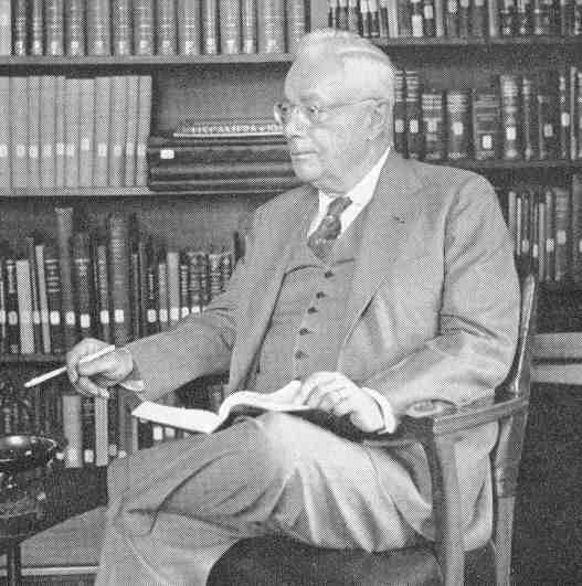
McMath (Figure 2) became one of the world’s leading authorities on solar physics in his later years. He gained great respect among his contemporaries not only as an innovative scientist but also as one who had the ability to get things accomplished. He was known for being a perfectionist, driven to succeed. He had little patience for delays, whether technical in nature or due to others. This gained him the reputation of being difficult to work with. He was also known to be fiercely loyal to his friends and respected colleagues.
Dr. McMath’s career path was anything but typical for an astronomer. McMath was born on the 11th of May 1891 in Detroit where he spent most of his life. His father, Francis C. McMath, had been quite successful in the bridge building industry. Planning to follow in his father’s path, Robert studied civil engineering and received his bachelor’s degree from the University of Michigan in 1913. During World Was I, he joined the Army Corp of Engineers. In 1919, after the war, he left the Army after gaining the rank of major. McMath spent some time working with his father designing bridges. A bridge accident convinced McMath that the bridge building business was not for him. McMath was working on the bridge that spanned the St. Lawrence River when it collapsed with him still on it! He escaped the bridge collapse with his life, never to return to that business (Pierce 2001). After leaving bridge building in 1922, he joined Motors Metal Manufacturing Company as Assistant Manager. Francis McMath and his associate, Willard Pope, owned controlling shares in the company. Robert’s father instructed him to prepare the company for liquidation. Ignoring his father’s instructions, McMath turned it into a highly profitable company. McMath would remain with the company until 1954, rising to the position of Chairman of the Board (Edmondson 1997).
McMath became a true insider in both the worlds of government and industry. He became friendly with the likes of Charles Lindberg, Henry Ford, and Joseph Dodge (Director of the Bureau of the Budget for President Eisenhower). McMath knew how things worked in government and industry and knew how to get things accomplished. If he needed to deal with a corporation, he wouldn’t waste time speaking to anyone below its Chief Executive Officer (Pierce 2001).
3.1 THE MCMATH-HULBERT OBSERVATORY
McMath, with his father and close friend, Judge Henry S. Hulbert, formed an idea that motion-picture technology could be used as an effective tool in education and popularizing astronomy. The technical challenges associated with motion photography of celestial phenomenon proved to be daunting. McMath’s engineering talents were drawn to these challenges and working on them first awoke his serious interest in astronomy. In 1929, the trio built a private observatory with a 10.5-inch (0.27-m) reflector telescope to experiment with astro-cinematography. They had some success with filming the motions of Jupiter’s atmosphere and its moons, a stellar occultation and the motions of shadows across craters on the Moon.
Their efforts gained the attention of the Department of Astronomy at the University of Michigan. The astronomers at the U. of M. helped their observing programs with technical assistance and shop time for their projects. This association eventually led to the McMath-Hulbert Observatory being donated to the University of Michigan and R. R. McMath becoming a member of the U. of M. Astronomy Department. He was also named the observatory’s director. McMath’s name appeared on 78 scientific publications during his astronomical career. He had earned the respect of the astronomical community even though his title of doctor was not earned through the normal academic route. His Doctor of Science degree was an honorary award from the Pennsylvania Military College in 1941. “Though he was never a professional astronomer in the ordinary sense of the word, honorary degrees were conferred by the University of Michigan, Wayne University, and Pennsylvania Military College” (Petrie 1962).
The McMath-Hulbert Observatory grew quickly under the direction of Dr. McMath. An instrument called a spectroheliokinemetograph was built for the observatory’s 0.27-m reflector to extend the motion-picture studies to solar prominences. This started the move of McMath’s career towards a specialization in solar astronomy. A 50-foot (15.24-m) solar tower telescope was erected in 1936 with technical assistance from the Mount Wilson Observatory staff. The telescope’s spectrograph extended another 9.4-m underground. A 0.6-m Cassegrain telescope was added in 1940. This was designed as a general-purpose telescope to which various instruments could be attached. The 0.6-m Cassegrain was named the F. C. McMath Memorial Telescope in honor of Robert’s recently deceased father.
One year later a second solar tower was constructed, this one 75-feet (21.3-m) tall. It received a new Vacuum Spectrograph in 1955 (University Lowbrow Astronomers 2000).
3.2
R. R. MCMATH’S LATER YEARS
McMath’s scientific reputation continued to grow. In 1945, he was made professor of solar physics for the University of Michigan and in 1951 he become professor of astronomy. He served as president of the prestigious American Astronomical Society between 1952 and 1954. McMath’s scientific reputation along with his connectedness in industry and government made him the natural choice in 1954 to head the NSF’s advisory committee on the National Astronomical Observatory. It is of little surprise that the panel’s recommendation to the NSF included construction of the world’s largest solar telescope as part of the national observatory.
McMath spent many years at the McMath-Hulbert with the dream of constructing the world’s largest solar telescope to probe the Sun’s secrets. The solar telescope project at Kitt Peak represented the realization of his long sought goal. He spent the last several years of his life deeply involved with the planning and development of this new solar telescope that would ultimately carry his name. Unfortunately, Robert McMath did not live to see its dedication. He died on the 2nd of January 1962, ten months before the formal dedication of (as it was then known) the McMath Solar Telescope.
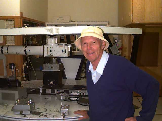
McMath’s failing health prevented him from making the trip to the solar telescope project on Kitt Peak more than a few times. He left the details of the project to his younger and trusted colleague, Dr. A. Keith Pierce (Figure 3).
4. DR. A. KEITH PIERCE
A. Keith Pierce was a graduate student in astronomy at the University of California at Berkeley in the early 1940’s. His education was disrupted by America’s entrance into World Was II. During the war, he worked for the Lawrence Radiation Laboratory. Pierce returned to Berkeley after the war to finish his doctorate in 1948. Dr. A. Keith Pierce found a position with the University of Michigan as Assistant Professor of Astronomy working as assistant to astronomer Dr. Leo Goldberg. Dr. McMath was sufficiently impressed with Pierce to have him transferred to the McMath-Hulbert Observatory as a staff astronomer. Dr. Pierce has always held McMath in the highest esteem; Pierce always refered to him as Dr. McMath and never addressed him by his first name (Pierce 2001).
It was natural for McMath to hire Dr. Pierce to help in the development of the very large solar telescope. One of Pierce’s earliest assignments for the fledgling observatory, in October 1956, was to visit several “solar observatories in England, Germany, and France to study their equipment, research programs, etc., but with particular emphasis on the solar seeing problem” (Pierce & McMath 1958). He spent two weeks at Pic du Midi in the Pyrenees where he learned about their program to improve the local seeing conditions.
 Pierce
became the primary scientist in charge of the development of the telescope from
its design to its construction. McMath recommended Pierce be appointed as the
Associate Director of the National Astronomical Observatory at an AURA
Executive Committee meeting on the 13th of September 1958. Dr. Pierce’s title
was later changed to Associate Director in charge of the Solar Division during
a reorganization of the observatory in March of 1960. (Dr. A. B. Meinel was
named as the Associate Director in charge of the Stellar and Space Divisions.)
Pierce
became the primary scientist in charge of the development of the telescope from
its design to its construction. McMath recommended Pierce be appointed as the
Associate Director of the National Astronomical Observatory at an AURA
Executive Committee meeting on the 13th of September 1958. Dr. Pierce’s title
was later changed to Associate Director in charge of the Solar Division during
a reorganization of the observatory in March of 1960. (Dr. A. B. Meinel was
named as the Associate Director in charge of the Stellar and Space Divisions.)
Dr. Pierce stayed with the Solar Telescope through the rest of his professional career. After the dedication of the McMath Solar Telescope, he remained at the observatory as an active solar researcher. Though now officially retired, Pierce is still an active observer at the telescope and holds the title of Astronomer Emeritus with the National Solar Observatory.
A ceremony was held on the 30th anniversary of the telescope’s original November 2nd, 1962, dedication to commemorate Dr. Pierce’s vital contributions to the development of the solar facility. It was rededicated on that day as the McMath-Pierce Solar Telescope Facility.
5. OPTICAL CONFIGURATION
The design of any device should start with the final product. The end product of a solar telescope is the solar image. The first step of designing the new solar telescope was to determine the optimal image scale. “Work on the spectra of solar granules, on the physical structure of sunspots and their associated magnetic fields, requires considerable image size. Past experience has shown that the optimum image of the sun should be approximately a yard (0.91-m) across” (McMath & Pierce 1960). Several optical designs were considered for the solar telescope design.
5.1
COUDE FOCUS CASSEGRAIN
The image scale required could easily be obtained at the Coude focus of a standard Cassegrain type telescope. The Cassegrain had the advantage of being a well-known design, very popular with stellar astronomers, that is compact enough to be mounted on a conventional equatorial mounting.
The Cassegrain was quickly rejected. It was felt that the intense heat load from a short focal length primary could distort the secondary mirror’s figure. The Cassegrain secondary mirror obstructs the optical path. The secondary blocks only a small portion of the incoming light but causes diffraction. The diffraction around the secondary degrades the telescope image quality.
5.2 COELOSTAT
A fairly common optical design for a solar telescope is the coelostat. A coelostat consist of a flat mirror that rotates about the equatorial axis at half the diurnal rate. The solar beam is reflected up to a secondary flat mirror that then diverts the beam, either horizontally or vertically, onto the imaging optics of the telescope.
The coelostat has the advantages of an unobstructed light path since the secondary mirror is placed above the coelostat to intercept the solar beam. Another advantage is that the image formed by the coelostat doesn’t rotate through the day.
There are several disadvantages of the coelostat design. The secondary mirror, or its support, will often cast a shadow across the coelostat at some time during the day losing a fair amount of observing time. The angle of the solar beam coming off of the coelostat changes through the year with the seasonal change of the Sun’s declination. The secondary mirror must be able to be raised or lowered to intercept the solar beam from the coelostat as the Sun angle changes through the seasons. This represents a complication and expense in the telescope design. The coelostat requires two mirrors to tack the Sun. Two mirrors obviously add to the costs of the telescope as well as decreasing throughput and contrast.
5.3 HELIOSTAT
The heliostat is the configuration that was eventually chosen for the solar telescope. Unlike the coelostat, the heliostat uses only a single mirror to track the Sun. The mirror is mounted equatorially and rotates with the celestial sphere, once per day. The heliostat can also move in declination. This mirror configuration reflects the solar beam down the telescope’s equatorial axis to the telescope’s imaging optics that are stationary and so require quite only simple mountings.
The downside of the heliostat is that its image rotates once per day. To compensate for the rotation, the instruments must be built in such a way that they can rotate at the same rate to compensate. This complication was felt to be a small price to pay for the heliostat’s other virtues – a single moving mirror system that doesn’t get shadowed during the observing day.
5.4
UNOBSTRUCTED OPTICAL DESIGN
The focal length required to produce the specified 0.9-m diameter prime focus solar image is about 90-m. This long focal length was used as an advantage by the designers to produce a fully unobstructed imaging system. It was determined that a1.52-m f/60 imaging mirror could be tipped as much as 2° off-axis to feed a folding flat mirror while introducing only 1/3 of an arcsecond of coma (Pierce & McMath 1958). The folding flat, #3 mirror, would then be completely out of the optical path between the heliostat and #2 imaging mirror avoiding the diffraction effects of a Cassegrain or Newtonian optical system.
Another benefit of a slow (large f/ratio) optical design is that there is no advantage to going to the added expense of parabolizing the mirror’s figure. The imaging mirror can be figured to a simple sphere.
The heliostat mirror must be larger than its #2, imaging mirror, if the solar beam is to fill the entire aperture of the #2 mirror. The heliostat tips upward in declination to reflect the solar beam down into the telescope. Tipping the heliostat back, in declination, foreshortens its projected size is in that axis. The heliostat diameter for the solar telescope was chosen to be 2-m. This would allow the heliostat to point as far north as -8.9° before under-filling the #2 mirror {DeclinationMax = 2cos-1(1.52/2.00) - 90°}.
The time of the year that the Sun’s declination is higher than -8.9°, the full aperture of the telescope is not utilized. This was considered to be an acceptable compromise. The unused aperture is not terribly large in comparison to the entire surface area of the #2 mirror and a larger heliostat mirror would have been prohibitively expensive at the time. The Sun’s declination is above -8.9° between 26 February and 16 October each year (Nautical Almanac Office 2000) and reaches a maximum declination of +23.44° on the summer solstice on July 21st. At least a part of this observing time is expected to be lost to the rainy Arizona monsoon season that typically begins in early July.
6.
BUILDING DESIGN
In the fall of 1957, Mr. William
F. Zabrinskie, a civil engineer from Detroit, was commissioned to prepare three
preliminary designs for the solar telescope building. All three designs are
conceptually quite similar. They all appear as very large right-triangular
structures with the heliostat mounted at the top of the vertical section. The
beam from the heliostat shines down the triangle’s hypotenuse, which is aligned
along the telescope’s equatorial axis. The imaging, #2 mirror, is located at
the bottom of the hypotenuse, which reflects back up toward the folding flat
mirror, #3, located just below the heliostat. The #3 was positioned out of the
way of the beam coming down from the heliostat making for an unobstructed
optical path. The #3 mirror diverts the beam downward to an air-conditioned
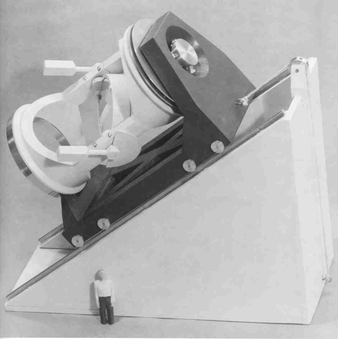
observing room located just below ground level (Figure 4). Spectrographs and
other instrumentation were to be mounted horizontally in the observing area
(Pierce 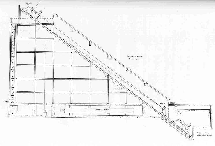
1957) along the bottom of the triangle.
The differences between the three designs were mostly in the style of framing that was to be used. One design called for a structure made from H-beams and columns, another used large steel tubes, while the third was designed to be constructed from reinforced concrete.
Mr. Zabrinskie thought that the triangular shape of the telescope structure made it appear like the index of a gigantic sundial. Because of this, he referred to the telescope building as the “Index Building”. Dr. McMath thought that while the structure was not “architecturally beautiful”, it was “functionally beautiful” (Pierce 1957).
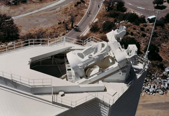
It is interesting to note how much of Zabrinskie’s preliminary design concepts survived to be incorporated into the final telescope structure. The final telescope structure retained the overall triangular shape. All of the optical mounts were placed on railroad-like tracks to enable them to be moved for focusing and easy servicing. The exterior of the structure was to act as a wind shield and was water cooled. All of these ideas from Zabrinskie’s designs can be seen in the final telescope structure (Figure 5).
Following Zabrinskie’s preliminary design work, AURA contracted with the Chicago engineering firm of Skidmore, Owings, and Merrill to study all possible structural designs for the solar telescope. Their studies were to include, but not be limited, to the designs done a year earlier by Zabrinskie.
Skidmore, Owings, and Merrill prepared ten designs for the telescope building. Of these ten, they recommended two for final consideration by AURA. One consisted of a tapered cantilevered tower that extended from the ground at the local latitude angle of 32°. This design has been described as appearing like an “extreme case of the leaning tower of Pisa” (Kloeppel 1983). The design may have been aesthetically beautiful but more expensive and less stable than the simpler tower structure that was adopted by AURA in June 1959.
6.1
FINAL DESIGN
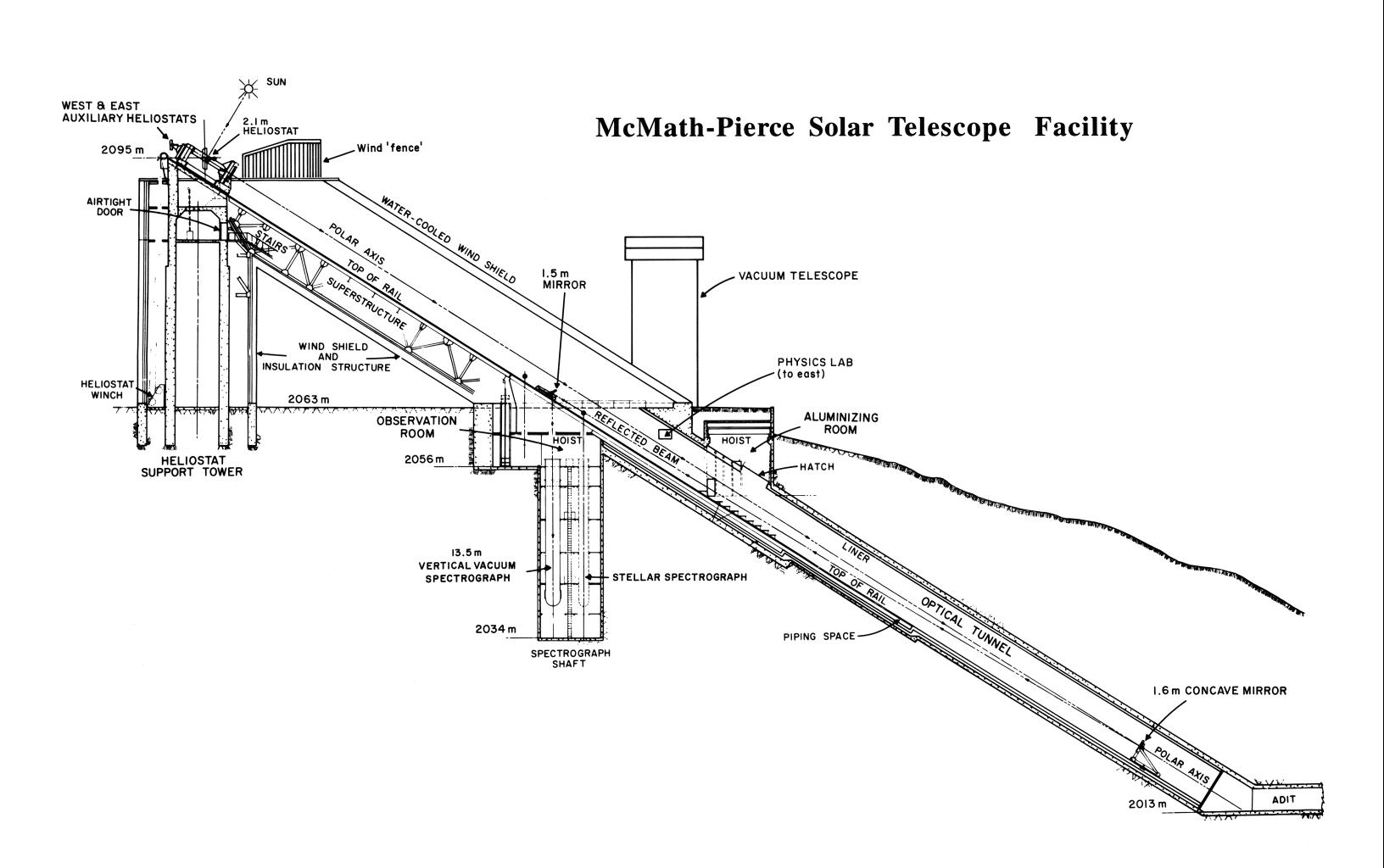 The
chosen design featured a vertical tower to support the heliostat. The heliostat
looks down a long shaft that is tipped along the equatorial axis, much as in
Zabrinskie’s preliminary concepts. Unlike in the initial conceptual designs,
the optical shaft extends below ground level for roughly another 90-m to the
#2, imaging mirror (Figure 5). The #2 mirror is tipped about 1 ¼° off
axis toward a third, folding flat, mirror that is located near the ground. The
#3 mirror diverts the beam vertically downward into the observing room, which is
just below ground level.
The
chosen design featured a vertical tower to support the heliostat. The heliostat
looks down a long shaft that is tipped along the equatorial axis, much as in
Zabrinskie’s preliminary concepts. Unlike in the initial conceptual designs,
the optical shaft extends below ground level for roughly another 90-m to the
#2, imaging mirror (Figure 5). The #2 mirror is tipped about 1 ¼° off
axis toward a third, folding flat, mirror that is located near the ground. The
#3 mirror diverts the beam vertically downward into the observing room, which is
just below ground level.
In Zabrinskie’s designs, the solar beam is also fed into the observing room from above, but is reflected off of a 4th mirror delivering a horizontal beam to the instruments. The final design delivers the image vertically, eliminating the need for a #4 mirror. This meant that the spectrograph tanks and other equipment had to be built vertically into the ground and had to be able to rotate around their vertical axes to compensate for the daily image rotation.
6.2
HELIOSTAT TOWER
Seeing is caused by light passing through air masses of differing temperature. The Sun heats the ground during the day creating thermals that deteriorate image quality. (This is obvious to anyone who’s gazed down a hot asphalt covered road.) It had been know for some time that temperature fluctuations decrease with height above ground. It was not known at what rate they decrease or how high one would need to go before the fluctuations are no longer of concern. “After light travels through the atmosphere the quality of the seeing should not be destroyed in the last few hundred feet near the focus” (McMath & Pierce 1960).
Staff astronomer William Livingston designed and constructed equipment to test temperature fluctuations at Kitt Peak as a function of height. Measurements taken with Livingston’s equipment indicated that temperature fluctuations decrease exponentially with height.
Temperature fluctuations at ground level were around 3° C. At a height of 55 feet (16.8-m) the temperature fluctuations were less than 0.4° and about 0.2° at 55-m. The temperature data indicated that the heliostat should be mounted as high as possible. The engineers wanted the heliostat tower to remain as short as possible for minimum costs and maximum rigidity.
Based on Livingston’s data and the costs estimates of building a tower, the height for the heliostat tower was chosen to be100 feet (30.5-m). The tower is a vertical concrete cylinder 7.9-meters in diameter with a wall thickness of 1.2-meters (Figure 6). The tower is protected from the wind by external cooling panels that are mounted to the structure’s framework. The framing of the outer structure is acoustically isolated from the tower. It was calculated that the tower deflection would be less than 0.4 mm in a 40 Kilometers/hour wind, which would move telescope’s primary image by less than 1/3 of a second of arc.
7. TELESCOPE COOLING
Great effort was taken in the design of the McMP to minimize the effects on the telescope's image quality by thermals crossing the optical path inside the telescope. Air heated by the solar beam will rise and break into turbulent flows in the telescope's optical tunnel. Since air masses at different temperatures have differing refractive indexes, a warm turbulent flow will distort the optical wavefront and blur the resulting image. The distortion due to the atmosphere inside the telescope is what is referred to as “telescope seeing”.
The telescope was designed to stabilize the seeing by carefully controlling the air temperature in the optical path. The system strives to get the bottom of the optical tunnel to around 10 - 12° F (5.6 – 6.7° C) below the outside ambient temperature. The temperature would then be allowed to rise steadily, to within a few degrees of ambient, towards the top of the telescope. It was believed that this steady temperature gradient would allow the air to rise very slowly through the optical path in a more-or-less laminar flow. “Irregular air temperature fluctuations in the optical tunnel, it should be noted, are ‘doubly troublesome’ because they influence not one but two light beams: both the beam coming down from the heliostat to Mirror No. 2 and the beam coming back up the tunnel from Mirror No. 2 to Mirror No. 3.” (Donovan & Bliss 1962). By looking through a smooth, laminar flow and by having only very small variations in the air mass temperature, the telescope's image quality would be maintained. The strategy for dealing with the telescope's excess heat load was separated into two independent cooling systems, one for the underground optical tunnel and the other for the portion of the structure that is above ground.
7.1 OPTICAL TUNNEL COOLING
SYSTEM
About two-fifths of the telescope’s roughly 150-m optical path was excavated below ground. (The ratio of the above to below ground portions of the telescope varies depending on which port and instrument the focus is delivered to.) The optical tunnel was cut through the south side of the mountain downward at an angle of 32 degrees (the local latitude) so that the tunnel points up toward the north celestial pole. The bottom, south end, opens out onto the southern slope of the mountain. Fans were installed at the bottom opening to allow outside air to be pulled into the telescope through the top and exhausted out of the south end opening.
The rock surrounding the optical tunnel stays at a fairly constant temperature of around 13° C throughout the year. This temperature was found to be low enough so that no additional cooling would be needed to stabilize the seeing in the warm Arizona summers. The ambient temperatures in winter can drop well below freezing for extended periods and so a chiller system was designed and installed.
The walls of the belowground optical tunnel are lined with aluminum panels, about 20,000 square feet (1858 m2), that are attached to a grid of over 7500 meters of water pipe, 2.5 cm in diameter. An insulating blank 3” (7.6 cm) thick was installed between the cooling pipes and the tunnel’s rock wall. The water pipes circulate a chilled 42% glycol and 58% water solution that is chilled by a 3-cylinder compressor rated to dissipate 160,000 Btu (1.688 x 10^8 joules). The glycol/water solution enters the grid of pipes at the bottom of the optical tunnel and exits through the top. The temperature of the liquid will warm steadily as it rises up the telescope optical path absorbing heat from the surrounding rock. This steady increase in temperature is just what is desired to create the stable air mass in the optical path. The chiller system is left off during the summer months. During the winter, there are inside and outside temperature gauges that regulate the compressor to keep the tunnel walls at the proper temperature.
7.2 ABOVEGROUND STRUCTURE COOLING
The aboveground structure is covered by roughly 30,000 square-feet (2787 m2) of panels. Several materials and paints were evaluated to test their absorption of heat from sunlight. A surface painted with white titanium dioxide pigment paint was found to warm by only 10 to 15° F (5.6 – 8.3° C) in full sunlight (McMath & Pierce 1960). Copper was chosen for the panel material due to its very high heat conductivity. Still, it was calculated that during midday, the Sun will heat the skin panels with about 80,000 Btu/hour (23.45 kilowatt-hours) in the winter and closer to 140,000 Btu/hour (41 kilowatt-hours) during the summer months (Donovan & Bliss 1962).
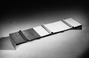 The
copper panels used to cover the telescope include built-in 1.27 cm diameter water
lines known as “Tube-in-Strip” (Figure 7). The exterior “Tube-in-Strip” panels
were covered with the white titanium dioxide pigment paint to minimize the
absorption of solar heating. A mixture of glycol and water is continuously
circulated through the Tube-in-Strip panels. The glycol cooling mixture is
pumped to a 16,000 gallon (60,566 liter) holding tank. This large holding tank
acts as a heat-mass for the telescope. The warm liquid returning from the
telescope skin mixes with the water and glycol in the tank and slowly warms the
tank liquid through the day. The temperature of the glycol coolant that flows
from the tank lags behind the climbing temperature by a few degrees through
most of the day. The cool glycol mixture enters the telescope at ground level
and warms as it makes it way upward through the skin and returns to the tank a
few degrees above ambient. This continues the steady climb in the temperature
inside the telescope all the way to the top where the air from the telescope
mixes with outside air with a very small temperature differential. The rate at
which the cooling liquid flows through the Tube-in-Strip panels is regulated by
temperature gauges that read the temperature difference between the liquid
flowing into and returning from the telescope.
The
copper panels used to cover the telescope include built-in 1.27 cm diameter water
lines known as “Tube-in-Strip” (Figure 7). The exterior “Tube-in-Strip” panels
were covered with the white titanium dioxide pigment paint to minimize the
absorption of solar heating. A mixture of glycol and water is continuously
circulated through the Tube-in-Strip panels. The glycol cooling mixture is
pumped to a 16,000 gallon (60,566 liter) holding tank. This large holding tank
acts as a heat-mass for the telescope. The warm liquid returning from the
telescope skin mixes with the water and glycol in the tank and slowly warms the
tank liquid through the day. The temperature of the glycol coolant that flows
from the tank lags behind the climbing temperature by a few degrees through
most of the day. The cool glycol mixture enters the telescope at ground level
and warms as it makes it way upward through the skin and returns to the tank a
few degrees above ambient. This continues the steady climb in the temperature
inside the telescope all the way to the top where the air from the telescope
mixes with outside air with a very small temperature differential. The rate at
which the cooling liquid flows through the Tube-in-Strip panels is regulated by
temperature gauges that read the temperature difference between the liquid
flowing into and returning from the telescope.
The circulation system continues to operate through the night. This allows the cooling liquid that was heated during the day to re-radiate its excess heat back to the cool nighttime sky. By morning, the temperature in the tank is back to ambient and the process is ready to begin once again. If the outside temperature climbs unexpectedly quickly, the fans at the bottom of the tunnel can be turned on to draw outside air into the telescope through the opening at the top.
8. HELIOSTAT WINDSCREEN
The telescope's 2-m heliostat was
completely exposed to the winds at the top of the telescope tower. The
telescope's best seeing was found during periods of light winds of less than
about 7 m/s. It is believed that these light winds kept a hot layer of air from
forming over the heliostat mirror surface. (A hot air layer would tend to
distort the wavefront moving through it.) Somewhat stronger winds, 7 to 15 m/s,
disturb the seeing only slightly. High wind speeds of 15 to 25 m/s were found
to shake the heliostat causing motion at the image plane. Image motion has a
similar effect to poor seeing on the image quality. The image motion due to
high winds was found to be relatively minor in the right ascension, 2.5 to 5
seconds of arc. The declination motion was much larger, up to 40 seconds of
arc.
 A novel and inexpensive solution to this
problem was found. A windscreen was erected around the heliostat. The
windscreen was modeled on a design developed for temporary telescope
installations such as for site surveys. The design is simple and only required
a few days of down time to install.
A novel and inexpensive solution to this
problem was found. A windscreen was erected around the heliostat. The
windscreen was modeled on a design developed for temporary telescope
installations such as for site surveys. The design is simple and only required
a few days of down time to install.
The design consists of vertical wooden
slats, around 0.2-m in width, with gaps between that are the same width as the
slats (Figure 8). Wind flowing through the vertical slats form eddies on the
leeward side. The kinetic energy in the
wind is dissipated in the eddies. The slight rise in air temperature due to the
energy dissipation in the eddies was calculated to be trivially small, 0.05° C with a wind speed of 10 m/sec. A solid wind fence would produce
a stagnant air mass around the telescope that would heat and would mix with the
cooler air above the fence in a turbulent flow (Hammerschlag & Zwaan 1973).
The windscreen was installed at the McMP
in 1986. The widths of the slats and gaps were made to be 1/40 the distance to
the heliostat mirror. The windscreen
wraps around the heliostat’s south side running from east to west forming a
U-shape. It is tallest to the south as the prevailing wind comes from the south
or southwest. It tapers in height to the east and west so that it never
obstructs the solar beam. The windscreen has been found to decrease the
heliostat declination windshake by at least a factor of ten (Pierce 1986).
9.
TELESCOPE OPTICS
Two of the original optics used in the solar telescope had a long, unique history. The General Electric Co. (GE) went to great deal of effort and expense trying to produce a quartz mirror blank for the Palomar 5-m telescope project in 1931. Quartz has many desirable characteristics as a telescope optical material. It is hard, relatively easily to figure, will accept a standard aluminum or silver coating, and has a very low coefficient of expansion compared to standard glass. The project was successful at producing three quartz disks, each about 1.6-meters in diameter, but was unable to scale their techniques up to produce a 5-meter diameter disk. GE ultimately abandoned the project and Corning was given the contract to produce a disk made from Pyrex that became the mirror for the great Palomar telescope.
The GE quartz disks were put into storage at their Lynn facility. Around 1950, GE decided to dispose of the disks. As far as they were concerned the old disks were useless. GE contacted Palomar Observatory to see if they wanted the blanks. Palomar was not interested but passed the information along to Dr. McMath at the McMath-Hulbert Observatory. McMath was able to get the blanks for the cost of their transport from GE to the McMath-Hulbert Observatory. There, they went back into storage until McMath offered them up to the Kitt Peak solar telescope project. McMath realized that it would take several years to get a 2-m mirror cast and polished for the telescope’s heliostat. In the meantime, one his quartz mirrors could be polished and used temporarily for the telescope’s heliostat. Although smaller in diameter than the planned 2-m heliostat, its use would allow the telescope to go into operation years earlier. The undersized heliostat would be replaced with a 2-m mirror when it became available (Kloeppel 1983).
Another of the quartz disks, 1.73-m diameter, was cracked during the annealing process. GE engineer, A. E. Ellis, was able to repair the cracked disk by “welding” it back together with a blowtorch. Ellis heated the mirror and filled the crack with molten quartz. This could have never been attempted with a normal glass disk. Glass would surely shatter with such non-uniform heating. Pierce & McMath (1958) stated that “its back surface, particularly near the edges, is in poor shape and rather large chunks can be removed by hand”. The disk was eventually cut down to 1.2-m in diameter to remove the worst sections by a monument works in Pasadena, California. The now 1.2-m disk was polished and put into service as the first #3 mirror in the McMP. Both of the quartz flat mirrors were polished in the optical shop of Mount Wilson and Palomar Observatories (AURA 1961).
The third quartz disk was full of bubbles and had a brick pattern from its mold in it. It was determined to be unsuitable for an astronomical mirror. Some other option would need to be found for the telescope’s #2 mirror - the imaging mirror.
9.1
METAL MIRRORS
Early astronomical reflecting telescopes used metal mirrors, normally made of speculum. These mirrors would tarnish quickly and require laborious repolishing. Since the discovery of the process to silver coat optics in the mid-1800’s, nearly all astronomical telescope optics have been made of glass, quartz or one of the ultra-low expansion ceramics such as Cervit.
A major concern in the design of the solar telescope was the heating of the mirror surfaces. At the elevation of Kitt Peak, a mirror is exposed to roughly 1.6 calories/cm2/min of solar radiation. The mirror’s thin reflective coating will reflect around 85% of this energy. The other 15% is absorbed into the coating. The energy is dissipated by convection and radiation away from the surface and conduction into the substrate. This non-uniform heating of the mirror will cause expansion of the substrate, distorting its figure and destroying the image quality (Pierce & McMath 1958).
Dr. McMath had a theory that a highly conductive substrate would keep the temperature gradient throughout the mirror quite small and preserved the optical figure. A program was undertaken to develop metal mirrors and to evaluate their viability for use as solar telescope optics.
Metal is not an amorphous material like glass. It tends to have internal stresses. There was concern that these stresses would not allow a metal mirror to maintain an optical figure. In 1960, the solar program purchased a 0.9-m aluminum mirror blank from Kaiser Aluminum & Chemical Sales, Inc. in Los Angeles, California. It was ground and polished at the AURA optical shop in Tucson and set up in the courtyard of the Tucson offices to evaluate the stability of its figure and how it coped with exposure to the Sun and the elements (AURA 1960). Aluminum is not a material that can be optically polished, so the mirror was coated with a 0.005-inch (0.13 mm) thick layer of Kanigen before the polishing. Kanigen is a chemically deposited amorphous nickel phosphide developed by General American Transportation Corporation of Chicago, Illinois in the late 1950’s. Kanigen is “exceptionally homogeneous and hard enough for polishing…The material appears to be well suited for a mirror base as far as scattering properties are concerned” (Pierce 1957).
The mirror was periodically tested. After eight months of sitting, it still held its figure. This success led to placing an order for a 1.52-m aluminum test mirror in May 1961 (AURA 1961a) from L & F Machine Co. in Los Angeles, California.
This was used as the first imaging mirror (#2) in the McMP telescope. The long-term performance of this aluminum mirror would determine whether the final 2-m heliostat mirror would be made from metal or from a more conventional material such as quartz.
The Tucson optical shop completed work on a 1.22-m flat mirror made of beryllium in 1966. This was used to replace the quartz #3 mirror of the same size that had been welded back together after cracking in the annealing oven at GE. The figure of the original mirror began to develop a ridge along the weld. This was apparently caused by stress in the weld. The mirror could have been refigured, but there was no guarantee that it wouldn’t again loose its shape. This was used as an opportunity to try beryllium as a mirror material.
9.2
NEW QUARTZ MIRRORS
 The
observatory received the first of two quartz mirror blanks ordered from Corning
in August 1965. The 1.6-m mirror was polished by the AURA optical shop and
became the second #2 mirror for the McMath telescope. The other blank ordered
from Corning was destined to become the 2-m heliostat to replace the temporary
1.6-m quartz heliostat. The telescope’s #2 mirror mount was modified to hold
both the aluminum and the quartz 1.6-m #2 mirrors on a turntable. The turntable
would allow the mirrors to be switched in about three minutes so that the
relative merits of each could be evaluated (AURA 1965a). The contract to modify
the #2 mirror mount went to Keystone Engineering of Los Angeles, California.
The mirror turntable was installed in January of 1966 (AURA 1966).
The
observatory received the first of two quartz mirror blanks ordered from Corning
in August 1965. The 1.6-m mirror was polished by the AURA optical shop and
became the second #2 mirror for the McMath telescope. The other blank ordered
from Corning was destined to become the 2-m heliostat to replace the temporary
1.6-m quartz heliostat. The telescope’s #2 mirror mount was modified to hold
both the aluminum and the quartz 1.6-m #2 mirrors on a turntable. The turntable
would allow the mirrors to be switched in about three minutes so that the
relative merits of each could be evaluated (AURA 1965a). The contract to modify
the #2 mirror mount went to Keystone Engineering of Los Angeles, California.
The mirror turntable was installed in January of 1966 (AURA 1966).
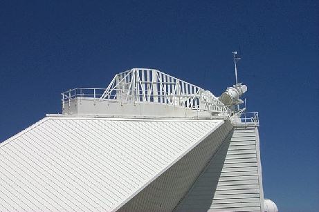
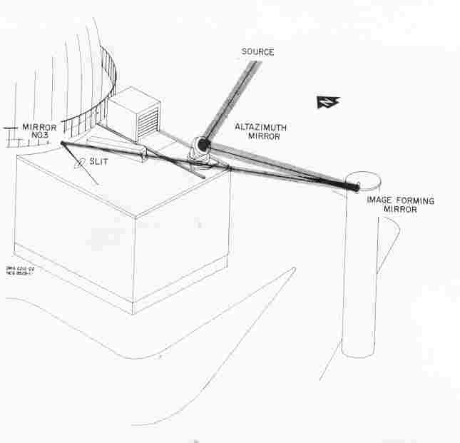
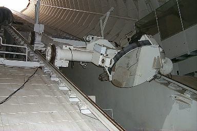
The temporary 1.6-m heliostat was not retired after being replaced by the 2-m mirror. The Kitt Peak 2.1-m telescope coude spectrograph was redesigned in 1971 with its own telescopic optical system (Figure 9). This allowed the coude spectrograph to be operated independently of the main 2.1-m telescope. The old 1.6-m quartz mirror was used in an altazimuth mounting to feed starlight to a 0.9-m image-forming mirror mounted in a tower just south of the 2.1-m telescope. The Coude spectrograph, used in its stand-alone mode, is about as efficient as it was when used with the 2.1-m telescope due its fewer number of reflections (AURA 1971a). The 1.6-m flat continues its long and varied career and is still making valuable contributions to astronomy.
9.3
EAST AND WEST AUXILIARY HELIOSTATS
An often-overlooked feature of the McMath telescope is that it was not only designed to be the world’s largest solar telescope, but at the time, it was to be the world’s three largest solar telescopes. On either side of the main optical path, two smaller heliostats were added to the telescope. Known as the East Auxiliary and West Auxiliary Telescopes, each has a 0.9-m heliostat and a 0.9-m imaging (#2) mirror with an f/ratio of approximately f/50. The auxiliary telescopes were designed to have roughly the same f/ratio as the main McMath telescope but with about half the focal length (and image scale). Instrumentation designed to work with the McMath’s beam should also work with the auxiliary telescopes.
An aperture stop in the optical paths limited the effective aperture of the telescopes to 0.8-m. At 0.8-m the twin telescopes were, for many years, tied as the second largest aperture solar telescopes in the world. The same engineering firm that designed the main heliostat, Charles W. Jones, designed the auxiliary heliostats.
 C.
W. Jones designed them to be mirror images of one another. Each heliostat would
be mounted on a fork mount. The fork would point upward toward the north
celestial pole. The solar beams would then be reflected down the optical tunnel
toward the south celestial pole where their #2 mirrors would reflect the beam
back up the tunnel and form an image in the observing room after being
reflected downward by their #3 mirrors. Each optical system looks much like the
main optical system but roughly half scale.
C.
W. Jones designed them to be mirror images of one another. Each heliostat would
be mounted on a fork mount. The fork would point upward toward the north
celestial pole. The solar beams would then be reflected down the optical tunnel
toward the south celestial pole where their #2 mirrors would reflect the beam
back up the tunnel and form an image in the observing room after being
reflected downward by their #3 mirrors. Each optical system looks much like the
main optical system but roughly half scale.
The heliostats were mounted above and to the two sides of the main heliostat carriage (Figure 10). Their appearance was described as looking like “ears on the main heliostat mounting” (AURA 1963). The heliostat forks are attached on their south ends to hollow polar shafts that are 0.8-m inside diameter. It is this that restricts the telescopes’ effective apertures. The shafts are hollow to allow the solar beams to pass through to the #2 mirrors to the south. The hollow polar shafts carry the right ascension bearings and worm wheels.
The request for bids from companies to manufacture the two heliostat mounts and drives was announced on 17 July 1961 and the bids were due by 11 September 1961. At $85,883.00, the well-known telescope manufacturer Boller & Chivens, Inc. was the low bidder and was awarded the construction contract. Boller & Chivens delivered the completed heliostats to AURA on 13 August 1963 (AURA 1963). The two heliostats were mounted onto the main heliostat carriage during the McMath telescope’s first annual maintenance shutdown in September 1963 (AURA 1963a).
The East Auxiliary went into operation with a 0.92-m diameter fused quartz heliostat mirror. The AURA optical shop completed the polishing of the quartz flat in January 1965 (AURA 1965). The heliostat fed the solar beam down to a 0.92-m Kanigen-coated aluminum spherical mirror with a 39-m focal length (Pierce 1969) and a 0.92-m aluminum folding flat mirror. The author believes, but hasn’t been able to document, that the 0.92-m folding flat mirror was the metal mirror that was polished and used to test the stability of metal mirrors before the 1.6-m aluminum disk was purchased for the main #2 mirror. All of the mirrors for the West Auxiliary would be made from the ultra-low expansion ceramic, Cervit (Pierce 1969) but wouldn’t become available until 1970. The West Auxiliary #2 and #3 mirror mounts were installed in the telescope in the fall of 1969 (AURA 1969). The West #2 Cervit mirror was figured 1.5° off axis to match the off axis angle of the #3 mirror. The system was found to deliver “very fine images, free of coma and astigmatism” (AURA 1970).
The East and West Auxiliaries have their own optical ports in the ceiling of the McMP Observing room so that their images can feed independent instruments in the observing room. All three of the McMP telescopes can be used fully independently of one another.
9.4
THE NUMBER 2 MIRROR INCIDENT
 The
3rd of November 1970 was scheduled to be a routine monthly
maintenance shutdown. The East Auxiliary #2 mirror was being lowered down the
telescope when its hoist cable slipped off of the drum. The carriage raced down
the tunnel incline about 30-meters before impacting the main #2 mirror
carriage! The East Auxiliary’s 0.9-m aluminum mirror broke free of its mounting
and fell another 5-meters onto the main #2 carriage. The 1.6-m main imaging
mirror was seen to “jump about 2 inches”. When the mirror settled back into its
support, the clips at the mirror edge broke a roughly 15-cm round chip from the
front edge (Figure 11).
The
3rd of November 1970 was scheduled to be a routine monthly
maintenance shutdown. The East Auxiliary #2 mirror was being lowered down the
telescope when its hoist cable slipped off of the drum. The carriage raced down
the tunnel incline about 30-meters before impacting the main #2 mirror
carriage! The East Auxiliary’s 0.9-m aluminum mirror broke free of its mounting
and fell another 5-meters onto the main #2 carriage. The 1.6-m main imaging
mirror was seen to “jump about 2 inches”. When the mirror settled back into its
support, the clips at the mirror edge broke a roughly 15-cm round chip from the
front edge (Figure 11).
The East #2 was destroyed, but the figure on the main #2 quartz mirror was unaffected. The telescope’s pupil image over-fills the diffraction grating in the Main Spectrograph so a chip at the mirror’s edge didn’t affect its data (AURA 1970b).
9.5
UPGRADING TO CERVIT
The debate over the relative merits of metal verses quartz mirrors had gone on for years with no clear winner between them. Kanigen-coated metal mirrors were found to be somewhat more difficult to maintain than glass. The reflective aluminum coating adhered quite well to Kanigen and was difficult to strip off for recoating without damaging the Kanigen (Harvey 2001). By the time of the incident that damaged the McMP #2 mirror, Corning had developed Cervit. Cervit was an ultra-low expansion glass-like ceramic that was clearly superior as a mirror material to both metal and quartz. Cervit had already been tried and found to work extremely well in the West Auxiliary telescope (AURA 1970). The decision was made to make the best of the situation by treating this as an “opportunity” to upgrade to Cervit. Cervit blanks were ordered to replace all three of the optics in the McMP main beam.
Cutting the cassegrain hole in the Cerro Tololo 4-m telescope’s primary mirror left a 1.06-m diameter Cervit disk. This disk was used to replace the destroyed East Auxiliary #2 mirror (AURA 1970b).
9.6
RETURN OF THE QUARTZ NUMBER 2 MIRROR
Several observers at the observatory felt that the Cervit #2 mirror didn’t deliver images with the quality they remembered from the earlier quartz mirror. It was believed that the Cervit mirror had a turned edge and a mask was sometimes put over the mirror to reduce the effective aperture by several cm. Some users believed that this would improve the image quality.
In the late 1980’s the mirror was pointed out of the door of the coatings lab while suspended from the lab’s ceiling-mounted crane. One of the telescope engineers set up a knife-edge tester on the roof of one of the residence houses on the mountain that happened to be located at the center of curvature of the 87-m focal length mirror. The knife-edge test revealed that the mirror did have a rolled edge. It also showed that the mirror had a central raised area.
The old quartz mirror was then tested in the same fashion and was found to have, aside from the large chipped area, a much better figure. The quartz mirror was reinstalled in the telescope and the Cervit mirror went into storage. The quartz mirror, chip and all, is still the imaging mirror being used in the McMP. Some observers have even commented that the chip is helpful when focusing the telescope’s pupil image inside of an optical setup. They find the chip is easier to focus on than a large, round, featureless image of a mirror.
9.7
INTEGRATED LIGHT FEED
The McMP produces an image of the Sun that varies between 822.7mm and 795.5mm depending on our distance from the Sun. The slit for the telescope’s Main Spectrograph is about 90mm long and is typically around 200 microns wide. The spectrograph only sees about 0.0036% of the solar disk at a time! The spectra from the Main Spectrograph represent only that very small area. Stellar astronomers never resolve the stellar disk of the star they’re looking at and so the light that enters their spectrographs represents the average of the entire star. To directly compare the solar spectrum to stellar, the astronomer would need to take spectrum at every position on the disk and average them together. This is clearly not a practical approach.
Solar staff astronomer Dr. William C. Livingston had an idea in 1967 for a simple approach that would allow the spectrum from the entire integrated solar disk to be taken at one time. Livingston’s concept was to beam non-imaged sunlight into the spectrograph. To accomplish this, Livingston mounted a couple of 0.25-meter flat mirrors onto the #3 mirror carriage. One mirror reflected the solar beam coming down the telescope from the heliostat up to the other. The second mirror then folded the light path down into the observing room. The light path went roughly in the shape of a “4”. This optical arrangement was referred to as the “Integrated Light” feed and the data with it was called “Integrated Light’ or “Sun as a Star” spectra (Livingston 2001).
Observing with this simple mirror arrangement was not convenient. Livingston’s Integrated Light pick-off mirror was not located along the equatorial axis of the main light path. The heliostat had to be tipped a bit off-axis to position the solar beam on to it. This caused the telescope not to track the Sun properly and required constant telescope drive corrections or use of an autoguider.
A few years later, an improved Integrated Light Feed mirror was designed and installed in the telescope by Kitt Peak engineers. This feed mirror used a 0.9-meter flat mirror mounted to the roof of the optical tunnel that could be lowered, with the push of a button, into the center of the light path in front of the normal #2 imaging mirror. The mirror mount was motorized to allow fine alignment to be done with a handpaddle from the observing room. The Integrated Light Feed remains a heavily requested configuration at the telescope.
10.
MIRROR MOUNTS
The colossal task of designing the
heliostat mounting and drive, along with the mounts and carriages for the #2
and #3 mirrors, was contracted to Charles W. Jones Engineering of Los Angeles,
California. The firm came to the project with considerable experience in large
telescope design. C. W Jones had been involved with the design of telescopes at
Mt. Wilson and Palomar and the 2.1-m telescope at Kitt Peak (US Naval
Observatory 1997). The mirror mountings and drives were built at the Sunnyvale,
California plant of the Westinghouse Electric Company. All three mirror
mountings were delivered to Tucson on railroad flat cars on the 9th
of August 1962 (AURA 1962).
10.1 HELIOSTAT MOUNT
 The
heliostat is a flat mirror that is mounted equatorially to track the Sun. It
must also be able to move in the declination axis to follow the changing height
of the Sun through the seasons. The design chosen for the heliostat drive was a
yoke style. The yoke is held by a bearing at the north and south ends of the
mount, with parallel arms running between that straddle the mirror. The south
bearing required a large opening through its center of rotation to allow the
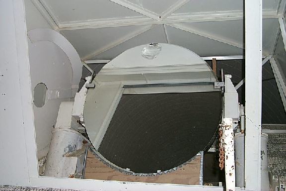
solar beam to pass to the telescope tunnel below (Figure 12). The hour angle
drive gear is also at the south end with the solar beam passing through its
center.
The
heliostat is a flat mirror that is mounted equatorially to track the Sun. It
must also be able to move in the declination axis to follow the changing height
of the Sun through the seasons. The design chosen for the heliostat drive was a
yoke style. The yoke is held by a bearing at the north and south ends of the
mount, with parallel arms running between that straddle the mirror. The south
bearing required a large opening through its center of rotation to allow the
solar beam to pass to the telescope tunnel below (Figure 12). The hour angle
drive gear is also at the south end with the solar beam passing through its
center.
The design of the lower (south) right ascension bearing that carries most of the yoke’s 12,000-kg weight, uses a large, 304-cm diameter, oil pressure pad bearing (Pierce 1964) similar to what was used for the Palomar 5-meter telescope’s “horseshoe” mount. The yoke carries the mirror cell that attaches at the declination bearings. Two motors are used in each axis; large DC motors for fast, slewing motions; and separate motors for the fine motions.
The declination slew motor uses a worm and gear, while the fine motions are accomplished with a tangent arm. Limit switches ensure that tangent arm can’t be driven beyond its limit of travel. “The right ascension drive consists of a synchronous motor driven at mean rate, which has superimposed on it, by means of a differential, incremented rotations from a stepping motor” (AURA 1962). The stepping motor introduced rate corrections to compensate for refraction through the Earth’s atmosphere.
Westinghouse produced a 720-tooth worm wheel gear for the right ascension drive. During installation, an inspection revealed that the worm had failed. The material had apparently been stressed during the case hardening process. It showed numerous hairline cracks, some extending through the teeth. The worm was estimated to only retain 10% of its strength (AURA 1962a). Westinghouse temporarily replaced the worm with another made of chrome-plated soft steel that was left over from the lapping of the original worm while they worked to produce a permanent replacement (AURA 1962b).
The heliostat tower doesn’t have a dome or other structure over the heliostat mirror to protect the mirror from the elements. The telescope was designed so that the entire 55,000-kg heliostat carriage could be lowered down inside the optical tunnel and a horizontal sliding door could be closed to protect against inclement weather. The process of lowering the carriage about 15-m down into the tunnel and closing the covers was expected to take about 20 minutes (Pierce 1964). It was quickly realized that moving the heliostat carriage induced a warping of the structure and binding in the right ascension bearing. The warping had to be corrected with the use a small hydraulic jack placed along the base of the carriage. Moving the heliostat carriage often was not a practical option in practice. An innovative solution was devised. The carriage would be left exposed on top of the tower. Nightly, the heliostat would be pointed straight downward. A cup-shaped cover was constructed on top of a hydraulic ram mounted below the heliostat carriage. The ram would lift the cover upward until it sealed around the edge of the heliostat mirror to protect it from the weather.
A mercury-filled tire-like bag was installed around the heliostat mirror in the summer of 1970. The mercury bag supports the mirror around its edge (AURA 1970a). The bag was designed such that the mirror effectively floats on the bag and is supported evenly around its edge no matter the orientation of the heliostat. The back support of the mirror cell was later fitted with a network of weights and levers meant to evenly support the mirror while pointing at any position on the sky.
10.2
NUMBER 2 MIRROR MOUNT
Charles W. Jones came up with a quite simple yet adequate mounting for the #2, imaging mirror. A carriage was welded together from 30-cm diameter heavy wall pipe. The mirror was supported across its bottom by a simple steel sling. The mirror, leaning back at the latitude angle of 32°, is supported from behind by a six pads. The telescope is focused by moving the entire carriage up or down the incline on the tunnel’s 12-foot (3.66-m) gauge track.
Originally, the 5,000-kg carriage was moved by a motor-driven ball screw that allowed for a focal travel of 2-m (Pierce 1964). To move farther, such as up the tunnel to the coating lab, the #3 mirror’s hoist was used (AURA 1962). The carriage was later given its own hoist to allow the focus to easily be moved over longer distances to deliver the image to multiple observing ports.
Collimation can be adjusted from the telescope’s observing room with a handpaddle that controls motors for moving the mirror horizontally and vertically.
10.3
NUMBER 3 MIRROR MOUNT
The #3 mirror could also be of a fairly simple design since the mirror only needs to be held motionless during observing. Its hoist is used to move the folding flat between the numerous observing ports in the telescope and to deliver the mirror to the aluminizing room for its periodic servicing. The mount holds the mirror on a fork that can be moved in two axes for collimation from a handpaddle in the observing room. The carriage rides up and down the telescope track on four wheels (Figure 13).
There are stops built into the side of the telescope, just inside and below the tracks, at each observing port. Tabs on the carriage are flipped down by hand before the carriage is lowered onto the stops at the desired port. The stops, not the hoist, hold the weight of the mirror carriage stably during observations.
11.
COATING LAB
About midway down the optical path, a bit south of the main observing room, is the telescope’s coating facility. It is located just below the division between the above and below ground cooling panels. The coating lab houses a large coating chamber from the F. J. Stokes Corporation of Philadelphia, Pennsylvania. It is used for periodic re-aluminizing of the telescope mirrors. The chamber was installed as part of the original telescope equipment and continues to be used. The chamber (Figure 14) was designed to accommodate optics as large as 2.1-m in diameter so that it could used for servicing the Kitt Peak 2.1-m Telescope and other smaller stellar telescopes. The 1958 proposal for the solar telescope included a budget of $25,000 for the coating chamber (AURA 1958).
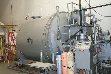 Four
large removable ceiling panels top the section of the optical tunnel next to
the coating lab. These panels can be removed and open into the coating lab. The
telescope optics can all be moved with their winches to below the opening into
the lab. A large roof mounted crane can then lift the mirror into the lab.
Four
large removable ceiling panels top the section of the optical tunnel next to
the coating lab. These panels can be removed and open into the coating lab. The
telescope optics can all be moved with their winches to below the opening into
the lab. A large roof mounted crane can then lift the mirror into the lab.
Once in the lab, the mirrors can be stripped of their old coatings, cleaned and lifted into the coating chamber. The chamber is oriented horizontally so that the mirrors can simply hang vertically in slings inside the chamber. A diffusion pump is used to evacuate that chamber to a few times 10^-6 torr. A current is applied to tungsten coils in the chamber and are heated to incandescence. This evaporates aluminum rods that were placed in the coils and deposits a thin layer of aluminum on everything inside the chamber, including the mirror surface (Poczulp 2001).
The lab’s location mid-way down the optical path makes access to the mirrors rather convenient. The mirrors never need leave the telescope structure. This minimizes the risk of damage due to handling and contamination of fresh coatings. The current optical coating technician that operates the lab, Gary Poczulp (2001), believes that “having coating facilities that are conveniently located to the telescope is something that seems often overlooked in modern designs”. He feels that the original designers came up with a “lab that is well laid out and is quite user friendly”.
The telescope is normally scheduled for a shutdown period of one to two weeks per year to remove and recoat any mirrors that have degraded due to exposure. The shutdown has normally been done during the summer rainy season. The rainy season, or monsoon, typically occurs between July and August.
The telescope mirrors are washed once or twice between the annual shutdowns. The procedure for washing a telescope mirror begins with rinsing the mirror thoroughly with a soapy water solution. The soapy water is a mixture of deionized water and a particular brand of horse shampoo - “Orvus” brand! This first rinse is meant to loosen and remove grit on the mirror surface. The mirror is then lightly rubbed with a natural sea sponge in circular motions, starting at the top and working downward. It is then rinsed thoroughly with deionized water to clean away all of the soap residue. The mirror is then dried by lightly and carefully patting with a lint-free paper towel. Great care is taken during the patting to ensure that the paper towel is not dragged across the mirror surface, which could scar the soft aluminum coating (Poczulp 2001).
12.
INSTRUMENTATION
The McMP telescope was designed as a general-purpose telescope for investigations into solar physics. The telescope is often used to feed a light beam into equipment brought by visiting astronomers. There were two primary instruments that were planned as part of the facility from the project’s beginning – a vertical spectrograph and a spectroheliograph.
12.1
MAIN SPECTROGRAPH
The Main Spectrograph (Figure 3) was planned to be the primary workhorse instrument for the McMP telescope. It has proved to be an extremely useful and versatile instrument that continues to be the telescope’s main instrument. The spectrograph was modeled on the very successful vacuum spectrograph at the McMath-Hulbert Observatory. The spectrograph is housed in a 1.8-m diameter, 21-m long vertical steel cylinder. The cylinder rests on a bearing at its base and is rotated with a clock-drive to match the 24-hour rotation rate of the telescope’s image.
The spectrograph uses a Czerny-Turner optical system. The spectrograph can use a selection of slits ranging in width from 60-microns to 300-microns depending on the required spectrographic resolution. The light passes through the slit and down to collimating mirror 13.7-m below, which reflects the beam up to the diffraction grating (Pierce 1969). The grating sends the dispersed beam back down to a second mirror, 13.7-m down, that focuses the spectrum at the top of the spectrograph tank where it is easily accessed by the detectors.
Horace W. Babcock, of Mt. Wilson Observatory, produced the grating. The grating has 610 grooves/mm covering a 25-cm by 15-cm area with a total number of lines equaling 155,000. The fifth order spectrographic resolution (l/Dl) as been measured to be approximately 500,000 at 5641Å, which is quite close to the theoretical value of 775,000 (Pierce 1964). The spectrograph can also be used in double pass mode. Double passing is accomplished by reflecting the exiting spectrum back through the optical path a second time, doubling the theoretical resolution.
The grating is mounted in a rotatable drum-like fixture that is suspended from the spectrograph’s top. Motors were installed that allow the grating to be rotated to and/or scanned across the wavelength of interest. The grating drum was modified in the mid-1990’s to include modern optical encoders and stepper motors that can more accurately find wavelengths under computer control. The original diffraction grating was replaced with a 632 grooves/mm grating produced by Milton Roy Optical. The new grating uses a Zerodur substrate and is larger than the original, 42 by 32 cm. The new modified drum includes a second diffraction grating that is mounted back-to-back with the original grating. This grating measures 47 by 36.8 cm with 120 grooves/mm and is optimized for the use in the infrared. Either grating can be selected by the throw of a switch, which flips the drum. The two gratings give the Main Spectrograph a spectral range of 0.29 – 12 microns.
12.2
SPECTROHELIOGRAPH
Dr. Keith Pierce and Dr. Robert Leighton, from the California Institute of Technology, jointly designed a spectroheliograph for the McMath telescope. The Spectroheliograph was built by Boller & Chivens and installed in November 1966 (AURA 1967). The instrument used a 25-cm slit and a 112-mm diameter grating in a 6-m vertical tank (Pierce 1969). Like the Main Spectrograph, the tank was made to rotate to compensate for image rotation. It was mounted vertically under its own observing port in the ceiling of the McMath observing room, 5-m south of the Main Spectrograph’s port.
The Spectroheliograph had a fairly short life. By the mid 1970’s, the primary staff user of the Spectroheliograph, Dr. Neil Sheeley, had left the observatory and interest in the instrument dwindled (Harvey 2001).
12.3
SOLAR-STELLAR SPECTROGRAPH
In 1983, the Spectroheliograph was rebuilt as a stellar spectrometer. Dr. Richard Dunn from Sacramento Peak Observatory redesigned the system to take high-resolution spectra of stars. By 1984, a full-time nighttime operator had been hired and a program of collecting spectra of “solar type stars” began (Giampapa 2001). Astronomers could submit proposals to the program. Proposals accepted by the Telescope Allocations Committee would be organized into a logical sequence by the operator who would collect the data for the astronomers. The astronomers’ data would be mailed to them on 9-track magnetic tape.
The spectrograph is of a conventional design with the exception of the input slit; it doesn’t use a slit. In its place is an image slicer. The image slicer is an optical device that accepts a square image and through internal reflections, slices the image up into five or ten wide slices, depending on which slicer is used. The slicer aligns each slice end-to-end creating the image of a slit while preserving all of the starlight falling on the input aperture. A normal slit would reject a large fraction of the starlight making the spectrograph less efficient.
The spectrograph began operation with a single-dimension Reticon array. In 1987, the detector was upgraded to an 800x800 pixel liquid-nitrogen cooled CCD from Texas Instruments. The CCD allowed spectra to be routinely taken of stars down to twelfth magnitude. A manually rotated drum selects between two gratings, a low dispersion grating and a high dispersion Echelle grating. Depending on grating and optics used, the spectrographic resolution (l/Dl) can vary between 21,000 and 100,000 (National Solar Observatory 1998).
The stellar program at the McMath telescope was declared to not be “central to the mission of the National Solar Observatory” and was officially closed in January 1995 to cut operations costs. The instrument continues to be used, mostly for planetary studies, but there is no longer an operator for the instrument on staff (Giampapa 2001).
12.4
FOURIER TRANSFORM SPECTROMETER
Dr. James Brault joined the observatory staff in the mid 1960’s. His training was as a physicist, not as an astronomer. Brault had a strong aptitude for instrumentation and computer programming. He applied his unique perspective and talents to improving upon the design of the Main Spectrograph. What he proposed was a radical departure from the grating spectrometers of the past. He pushed for and ultimately headed a program to develop and build the 1-meter path difference Fourier Transform Spectrometer (FTS) at the McMP Telescope.
 An
FTS is inherently different from a standard spectrometer. It has no diffraction
grating. Instead, it uses a scanning Michelson Interferometer (Figure 15) to
produce an interferogram of the light entering the instrument. The
interferogram is the plot of the intensity seen at the instrument’s output
verses the path difference between the retro-mirrors in the interferometer.
Applying the Fourier Transform to the interferogram reveals the spectrum.
An
FTS is inherently different from a standard spectrometer. It has no diffraction
grating. Instead, it uses a scanning Michelson Interferometer (Figure 15) to
produce an interferogram of the light entering the instrument. The
interferogram is the plot of the intensity seen at the instrument’s output
verses the path difference between the retro-mirrors in the interferometer.
Applying the Fourier Transform to the interferogram reveals the spectrum.
The FTS has several advantages over a grating spectrometer. The spectrum it produces is very wide-range and has extremely high wavelength accuracy. It doesn’t suffer from any of the inaccuracies from errors in the ruling of a grating. The FTS uses a circular input aperture (up to 1-cm diameter), which has a much larger collecting area than a grating spectrometer’s input slit making it very efficient. The spectrographic resolution of an FTS is limited only by the maximum path difference that the retro-mirrors can achieve (see appendix 1).
A major difficulty in designing an
FTS is controlling the retro-mirrors, whose position must be known at all times
to within a fraction of a wavelength the light. This difficulty was overcome in
the Kitt Peak FTS by mounting the retro-mirrors in massive carriages that ride
on oil bearings and are moved with linear electric motors. The positions of the
mirrors are 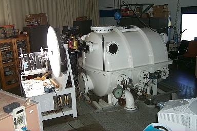 tracked
using of two separate laser interferometers. The entire instrument is housed
inside of a large vacuum chamber (Figure 16) to avoid acoustic and microthermal
disturbances (AURA 1971). It uses four sets of optics to cover from 250 nm in
the ultraviolet to 18 microns in the infrared.
tracked
using of two separate laser interferometers. The entire instrument is housed
inside of a large vacuum chamber (Figure 16) to avoid acoustic and microthermal
disturbances (AURA 1971). It uses four sets of optics to cover from 250 nm in
the ultraviolet to 18 microns in the infrared.
Brault began studies of the theory and design of the FTS in the late 1960’s. Construction began in 1971 (AURA 1971). A new observing room had to be constructed to house the instrument. Construction began on the new lab in 1969, which is located to the southeast of the main observing room (AURA 1969). The telescope’s #3 mirror is moved down the tunnel to just below what is now the Stellar Spectrograph port and is rotated eastward to feed the solar beam horizontally into the FTS.
The FTS has been in continuous operation at the telescope since 1976. It is still a very heavily subscribed instrument. It is used about half of the time as a solar spectrometer with the McMP telescope and about half of the time by physicists and chemists as a stand-alone laboratory spectrometer.
13.
INFRARED CAPABILITY
Tremendous effort in the design of the McMP went into cooling and stabilizing the air temperature and flow inside of the telescope to minimize its distorting effects on the image. The astronomers at the Sacramento Peak Solar Observatory in New Mexico had a very different concept for dealing with this problem. If air inside of the telescope is such a problem, why not get rid of it? From this very simple concept came the design of the Sacramento Peak Vacuum Tower Telescope (now known as the Richard B. Dunn Solar Telescope), which was constructed in the 1960’s and dedicated in 1969 (National Solar Observatory 1996). The vacuum tower telescope mounts all of its optics inside of a very large vertical vacuum tank, with a window at its entrance and exit. The air is evacuated from the tank and the problem of internal seeing is eliminated. So sharp were the images formed from this type of solar telescope, that almost every large solar telescope built since then has been based on the vacuum tower concept (Livingston 2001).
The vacuum tower design necessitates the use of at least two transmitting optics, the entrance and exit windows. These windows work fine in the visible spectrum but become opaque in the infrared past around 2.5-microns. This was considered an acceptable compromise when the only astronomical imagers available worked in the visible spectrum. Infrared array detectors began to become available to the astronomical community in the early 1990’s and suddenly a new wavelength band was opened to astronomical research. The vacuum solar tower telescopes, although still performing very well in the visible spectrum, were excluded from this new innovation.
Solar astronomers quickly realized that the McMP was the only large all-reflecting solar telescope available. The McMP was suddenly thrust into the position of being the default facility for infrared solar astronomy. A high percentage of the current programs on the telescope emphasize its infrared capabilities.
14.
EXAMPLES OF CURRENT PROGRAMS
McMP Telescope time is allocated on a competitive basis. Astronomers from around the world are invited to submit observing proposals, which are graded and sorted by their scientific merit by the Telescope Allocations Committee. The telescope schedule is then arranged to accommodate as many of the proposals as possible starting with the highest-graded proposals. This leads to a very diverse range of programs on the telescope. Below are some examples of current programs using the unique capabilities of the McMP.
14.1 MOLECULAR CLOUDS OVER
SUNSPOT UMBRAE
Dr. T. Alan Clark from the University of Calgary, Canada, has used the McMP with its 256 x 256 pixel near-infrared array detector and the Main Spectrograph to create spectroheliograms of molecular absorption lines in the 4-micron region. Molecules of particular interest include H2O, and HCl that only form over the coolest region of the sunspot umbra (Figure 17). Determining the temperature threshold for the formation of these molecules “should lead to a method for defining the temperatures of sunspot umbrae more precisely” (Clark et al. 2001).
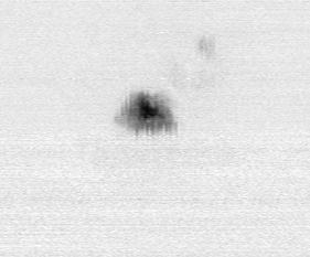
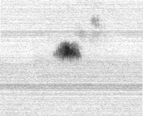
14.2
SODIUM EMISSION FROM MERCURY
 Dr.
Drew Potter uses the McMP Solar-Stellar Spectrograph to map the distribution of
sodium emission from the planet Mercury. An image slicer, described earlier, is
used to dissect the view into one arcsecond blocks. A total area of 10 square
arcseconds allows the entire planet to be imaged. The spectrograph is used to
analyze the intensity of the sodium D2 line emission in each block.
An image can be assembled from the spectra of the sodium distribution across
the planet. The image (Figure 18) shows the illuminated side of the planet
Mercury on the right with the terminator cutting across the left. The image
clearly shows a higher emission (red) on the hot illuminated side than on the
cooler dark (blue) side (Potter 2001).
Dr.
Drew Potter uses the McMP Solar-Stellar Spectrograph to map the distribution of
sodium emission from the planet Mercury. An image slicer, described earlier, is
used to dissect the view into one arcsecond blocks. A total area of 10 square
arcseconds allows the entire planet to be imaged. The spectrograph is used to
analyze the intensity of the sodium D2 line emission in each block.
An image can be assembled from the spectra of the sodium distribution across
the planet. The image (Figure 18) shows the illuminated side of the planet
Mercury on the right with the terminator cutting across the left. The image
clearly shows a higher emission (red) on the hot illuminated side than on the
cooler dark (blue) side (Potter 2001).
14.3 ZEEMAN SPLITTING IN OH AT 12 MICRONS

Dr. Don Jennings of NASA Goddard Space Flight Center used the McMP FTS in January 2001 to measure Zeeman splitting in sunspot spectrum of the hydroxyl radical (OH) (Figure 19). “Splittings in these lines are of interest not only as a probe of magnetic fields but also because the Zeeman effect is rarely seen in molecules” (Jennings & Plymate 2001). Zeeman splitting is proportional to the wavelength. Longer wavelengths exhibit greater splitting. To measure weak magnetic fields, it is desirable to use spectra taken as far into the infrared as is possible.
The two Zeeman components were recorded separately using a quarter-wave plate and a linear polarizer setup in front of the FTS. The difference of the two spectra are shown in the accompanying figure. (See Appendix II for a more in-depth explanation of Zeeman splitting.)
15.
THE FUTURE
Plans are progressing to build the next generation solar telescope, the Advanced Technology Solar Telescope (ATST). ATST is planned as the successor to both the McMP at Kitt Peak and the Dunn Solar Telescope at Sacramento Peak. It is to be a 4-m class all reflecting infrared solar telescope that will utilize adaptive optics and state-of-the-art instrumentation to support the research requirements of the solar astronomical community of the 21st century (National Solar Observatory 2001). The project is still in its infancy. What the ATST design will eventually look like and even where it will be placed is not yet known. Conceptual designs and possible site locations are currently being evaluated.
Over the short term, the McMP continues to be the only available facility for infrared investigations of the Sun. Current plans are to continue support of operations and upgrades consistent with the funding constraints during development of ATST. This indicates that the McMP will continue operations through at least the first decade of the 21st century. The telescope upgrades will be mostly aimed toward enhancing the telescope’s unique infrared capabilities.
15.1
A NEW INFRARED ARRAY DETECTOR
The primary infrared instrument for the solar telescope is the Near Infrared Magnetograph (NIM). The NIM uses the Main Spectrograph with some polarization optics mounted before the input slit. The output from the spectrograph is reimaged onto an Indium Antinomide (InSb) infrared array that is sensitive between 1 and 5 microns. The array is a commercial quality 256 x 256 imager that was purchased in the early 1990’s from Amber Engineering, Inc. The array is rather small by modern standards; it has many bad pixels and is known to be a “noisy” array. This is the same array that was used by Clark to produce the sunspot umbrae molecule cloud spectroheliograms discussed earlier.
A project has been funded that will replace the old Amber array with a 1024 x 1024 “Aladdin” InSb array built by Raytheon that will have much lower noise and a shorter readout time. The new array will require all new control and readout electronics. This new array will greatly expand the capabilities of the NIM program and should stimulate numerous new proposals from within the solar community. The new array should be operational in 2003 (Rabin 2001).
15.2
LOW ORDER ADAPTIVE OPTICS
Improving the quality of the image is another
primary goal. The telescope scientist for the McMP, Dr. Christoph Keller, has
begun an adaptive optics (AO) project for the telescope. The goal of this AO
program is to correct for atmospheric seeing and telescope aberrations to the
diffraction limit in the infrared. Limiting the system to the infrared
simplifies the design by only requiring correction of low order aberrations. A
low order adaptive optical system requires fewer actuators for the deformable
mirror that corrects the wavefront. Fewer actuators simplify the computational
needs, etcetera. Dr. Keller 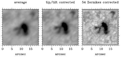 believes
that the entire program can be done for $25,000 spread over a few years. The
low costs are achieved by using as much off-the-shelf technology as possible.
believes
that the entire program can be done for $25,000 spread over a few years. The
low costs are achieved by using as much off-the-shelf technology as possible.
A proof of concept test was performed on the telescope using two CCD cameras taking simultaneous images. One camera recorded the primary image while the other was used to measure the wavefront distortion through a Shack-Hartmann subaperture array. Dr. Keller was able to deconvolve the wavefront errors from the image and produce a corrected image (Figure 20) that “is a good approximation of what an adaptive optics system with the same wavefront sensor would deliver” (Keller & Plymate 2000). A deformable mirror has been purchased and is being evaluated. It is hoped that a prototype system will be working at the telescope by 2003.
16.
CONCLUSION
The McMP is about to enter its fifth decade of service. It has a long and distinguished career, but it isn’t time to think of retirement just yet. There is still much science to be done. The telescope can deliver its beam to any of several observing ports including both the main observing room and southeast or FTS observing room. This allows a beam to be delivered to not only the telescope’s primary instrumentation that was discussed earlier, but to several general purpose observing ports. Astronomers find the telescope extremely convenient for setting up and testing prototype instrumentation. Many think of the telescope more like an optical lab that has as a special feature the ability to deliver a telescopic image than a conventional telescope where all instrumentation must be designed and ready to mate to a specific instrument port.
The telescope will continue to serve the solar astronomical community as the workhorse infrared facility until it is at last replaced by ATST. In the meantime, the McMP will serve as the test bed for much of the ATST development.
It is harder to guess what might
become of the McMP once the ATST in online. It is expected that the National
Solar Observatory will not be able to continue to afford the costs associated
with supporting the McMP after that point. This does not necessarily mean that
the telescope will be left abandoned to slowly rust away into history. A more
likely scenario is that the operation of the telescope will be given over to
some other institution or consortium that will to continue its use for research
and/or development. The McMath-Pierce Solar Telescope is still a unique
facility that offers unique capabilities to the scientific community. The
primary mission of the McMP may evolve with time, but it will likely continue
making contributions to science for quite some time to come.
REFERENCES
AURA, Proposal to the National Science Foundation from Association of Universities for Research in Astronomy, Inc. for the Construction of the World’s Largest Solar Astronomical Telescope, AURA, August 1958
AURA, Kitt Peak National Observatory, Monthly Report, August 1960
AURA, Kitt Peak National Observatory, Monthly Report, January 1961
AURA, Kitt Peak National Observatory, Monthly Report, May 1961a
AURA, Kitt Peak National Observatory, Monthly Report, August 1962
AURA, Kitt Peak National Observatory, Monthly Report, September 1962a
AURA, Kitt Peak National Observatory, Monthly Report, October 1962b
AURA, Kitt Peak National Observatory, Monthly Report, August 1963
AURA, Kitt Peak National Observatory, Monthly Report, September 1963a
AURA, Kitt Peak National Observatory and Cerro Tololo Inter-American Observatory, Monthly Report, January 1965
AURA, Kitt Peak National Observatory and Cerro Tololo Inter-American Observatory, Monthly Report, July and August 1965a
AURA, Kitt Peak National Observatory and Cerro Tololo Inter-American Observatory, Monthly Report, January 1966
AURA, Kitt Peak National Observatory and Cerro Tololo Inter-American Observatory, Monthly Report, January and February 1967
AURA, Kitt Peak National Observatory and Cerro Tololo Inter-American Observatory, Monthly Report, September and October 1969
AURA, Kitt Peak National Observatory and Cerro Tololo Inter-American Observatory, Quarterly Report, April-May-June 1970
AURA, Kitt Peak National Observatory and Cerro Tololo Inter-American Observatory, Quarterly Report, July-August-September 1970a
AURA, Kitt Peak National Observatory and Cerro Tololo Inter-American Observatory, Quarterly Report, October-November-December 1970b
AURA, Kitt Peak National Observatory and Cerro Tololo Inter-American Observatory, Quarterly Report, July-August-September 1971
AURA, Kitt Peak National Observatory and Cerro Tololo Inter-American Observatory, Quarterly Report, October-November-December 1971a
Clark, T. A., et al. 2001, NOAO Newsletter, 66, In Press
Donovan & Bliss, The Cooling System of the Kitt Peak Solar Telescope, Technical Report 62-1, 15th June 1962
Edmondson, F. K., AURA and its US National Observatories, Cambridge University Press (1997)
Giampapa, M. S., Deputy Director, National Solar Observatory, Tucson, Arizona, 2 May 2001
Hammerschlag, R. H. & Zwaan, C. 1973, PASP, 85
Harvey, J., Astronomer, National Solar Observatory, Tucson, Arizona, 3 May 2001
Jennings, D. & Plymate, C. L. 2001, NOAO Newsletter, 66, In Press
Livingston, W. C., Astronomer Emeritus, National Solar Observatory, Tucson, Arizona, 6 April 2001
Keller, C. & Plymate, C. L. 2000, NOAO Newsletter, 63
Kloeppel, J. E., Real of the Long eyes, Univelt Inc. (1983)
McMath, R. R. & Pierce, A. K. 1960, S&T, 20, 2
Nautical Almanac Office, The Astronomical Almanac for the Year 2001, U.S. Government Printing Office (2000)
National Solar Observatory, Richard B. Dunn Solar Telescope, http://nsosp.nso.edu/dst/, 8 April 1996
National Solar Observatory, Solar Stellar Spectrograph, http://nsokp.nso.edu/mp/aboutstarspect.html, 2 July 1998
National Solar Observatory, Advanced Technology Solar Telescope, http://atst.nso.edu/, 2 May 2001
Petrie, R. M. 1962, S&T, 23, 4
Pierce, A. K., Progress Report on the 60” Solar Telescope, Report #3, July 1957
Pierce, A. K. &
McMath, R. R., Plan for a Large Solar Telescope of 60” Aperture and 300 Feet Focal
Length, AURA, Inc., Technical Report No. 1 (Solar Project), January 1958
Pierce, A. K. 1964,
Applied Optics 3, 12
Pierce, A. K. 1969,
Solar Physics 6
Pierce, A. K. 1986,
Solar Physics 107
Pierce, A. K., Astronomer Emeritus, National Solar Observatory, Tucson, Arizona, 6 April 2001
Poczulp, G., Senior Technical Associate, National Optical Astronomy Observatory, Tucson, 4 April 2001
Potter, A. E., Visiting Scientist, National Solar Observatory, Tucson, Arizona, 24 May 2001
Rabin, D. M., Solar Branch Chief, NASA Goddard Space Flight Center, Greenbelt, Maryland, 11 May 2001
University Lowbrow Astronomers, The History of the McMath-Hulbert Observatory, http://www.umich.edu/~lowbrows/history/mcmath-hulbert.html, May 2000
US Naval Observatory, USNO Flagstaff Station – History, http://ftp.nofs.navy.mil/about_NOFS/hist.html, 1997
APPENDIX I
In this section, an attempt is made to explain how a Fourier Transform Spectrometer works in as simple to understand and as concise a form as is possible.
 First,
consider a Michelson interferometer that has a collimated monochromatic
incoming light source, such as a laser. The entering wavefront will be split
into two by the beamsplitter, reflect off of the retro-mirrors and recombine
back at the beamsplitter. Assuming that the two retro-mirrors are at equal
distance from the beamsplitter, the recombining wavefronts will be in phase and
will constructively interfere. Viewing the beamsplitter, one would see a bright
spot (figure 21).
First,
consider a Michelson interferometer that has a collimated monochromatic
incoming light source, such as a laser. The entering wavefront will be split
into two by the beamsplitter, reflect off of the retro-mirrors and recombine
back at the beamsplitter. Assuming that the two retro-mirrors are at equal
distance from the beamsplitter, the recombining wavefronts will be in phase and
will constructively interfere. Viewing the beamsplitter, one would see a bright
spot (figure 21).
Moving one of the retro-mirrors forward or back by a quarter of a wavelength (l/4) would increase its total optical path to and from the retro-mirror by a half wavelength (l/2). The recombining wavefronts would now be out of phase causing destructive interference and the spot would be dark. Move another quarter wavelength and the beam would again become bright. A plot of the spot intensity verses path difference (Figure 22) shows that the intensity will trace out a continuous sine curve. The distance the retro-mirror moves can be deduced by simply knowing the wavelength of the laser and counting the number of cycles of bright to dark (called fringes). This is how a distance measuring interferometer works.
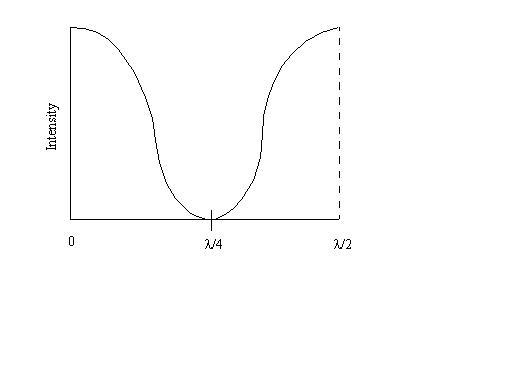
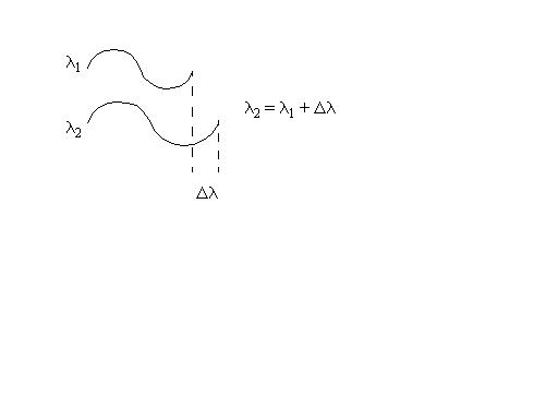
Now assume that the entering beam is not monochromatic, but is made up of two wavelengths, l1 and l2, that are very close to each other in wavelength such that l2 = l1 + Dl (Figure 23).
Start moving the retro-mirror from its zero path difference position. Both wavelengths begin in phase with each other. With each passing fringe, the two will become more out of phase. After some number of fringes, depending on the size of Dl, the l1 and l2 will become completely out of phase and no fringes will be seen. Continue moving and the fringes will increase again in contrast until l1 and l2 are again in phase. This is the point where the retro-mirror has moved exactly one less l2 half wavelengths than l1 half wavelengths. Stated mathematically:
n l2 = (n+1) l1
Rearranging: l2 / l1 = (n+1)/n
Substituting: (l1 + Dl) / l1 = (n+1)/n
1 + Dl / l1 = 1 + 1/n
Dl / l1 = 1 / n
Flipping: l / Dl = n
Remember that l / Dl is the definition of spectrographic resolution. This equation states that the spectrographic resolution of an FTS is determined solely by the number of wavelengths that the path difference (equal to twice the movement of the retro-mirrors) changes.
It would be relatively trivial to determine the two wavelengths that produced the fringe pattern above. The more wavelengths that are present makes for a fringe pattern, or interferogram, that is ever more difficult to interpret. There is a mathematical procedure known as the Fourier Transform (FT) that will determine all wavelengths present in the interferogram. By using a computer to perform an FT on the interferogram, the spectrum of light entering the FTS can be determined.
APPENDIX
II
Some spectral lines are sensitive to magnetic fields. These lines, in the presence of a magnetic field, will broaden or split into two. The width of the splitting is dependent on the strength of the magnetic field. This is what is known as the Zeeman effect.
The two Zeeman components are circularly polarized. One side is polarized clockwise while the other is polarized counter-clockwise. One can take the spectrum of each polarization component independently by using a quarter wave plate to convert the circular polarization states into orthogonal linear polarization. Then a linear polarizer can be rotated to select each of the states, one at a time. Subtracting the two polarization spectra cancels the non-Zeeman lines and leaves a characteristic looking down and up pattern (Figure 24). By measuring the separation between the down and up lines, the magnetic field strength can be determined.